
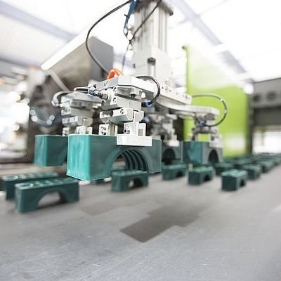
STAUFF CLAMPS
STAUFF CLAMPS IN STOCK
STAUFF Clamps have stood for quick, easy, and secure installation of pipes, tubes, hoses, cables, and other flexible and rigid components with outside diameters up to 1,016 mm / 40 inch for more than 50 years.
Their vibration and noise reduction capabilities are regarded as a significant contribution to environmental protection as well as occupational health and safety.
One of STAUFF's numerous unique capabilities is the processing of fire-resistant clamp body materials that have been tested and authorized according to many international fire-protection standards (such as BS 6853, EN 45545-2, and UL 94).
Even for tailored solutions based on customer specifications or in-house development, STAUFF promises timely response.
Independent certificates and approvals can be obtained for specific types and series:
-
American Bureau of Shipping
-
Bureau Veritas
-
Germanischer Lloyd
-
Lloyd’s Register of Shipping
STAUFF uses the STAUFF Zinc/Nickel surface coating for the finishing of its carbon steel pipe, tube, hose, and cable clamps, as well as metal accessories. The STAUFF Zinc/Nickel surface coating has been proven successful for many years. It offers reliable surface protection, even after transportation, handling, and assembly, and it complies with all current legal standards.
V2A and V4A stainless steel versions are commonly available from stock. On request, alternative materials and surfaces are available.
STAUFF Zinc/Nickel Coating
The STAUFF Zinc/Nickel surface coating provides outstanding surface protection – even after transit, handling, and assembly – with at least 1200 hours of red rust resistance. Testing in a salt-spray chamber according to DIN EN ISO 9227 proved this.
Users in all industries and applications benefit from sophisticated technology that has been developed for and used by the extremely demanding automobile industry for many years and has been the proven standard for a substantial number of STAUFF components since 2007.
-
Resistance against red rust / base metal corrosion for at least 1200 hours in a salt-spray chamber under real-world conditions, according to DIN EN ISO 9227.
-
The only sign of white rust is a little grey haze.
-
Exceeding the standards of the VDMA's corrosion protection class K5 (360 hours resistance to white rust / 720 hours resistance to red rust).
-
Cr-free hexavalent chromium (VI)
-
ELV compatible in accordance with 2000/53/EC (End of Life Vehicles Directive)
-
REACH-compliant (Registration, Evaluation, Authorization, and Restriction of Chemicals) pursuant to Regulation 1907/2006/EC
-
RoHS compliant in accordance with Directive 2002/95/EC (Restrictions of the Use of Hazardous Substances)
-
Color scheme is appealing, with a bright semi-gloss surface quality that is close to stainless steel.
-
Corrosion caused by interaction with other metals is significantly decreased (such as Aluminium and Stainless Steel)
-
Abrasion resistance is improved due to the coating's ductility and plastic deformability.
-
Nickel release is a fraction of the statutory limits for objects that come into direct and prolonged contact with the skin (independent results of the reference test technique according to DIN EN 1811 are available on request) and has little to no danger of provoking allergies.
-
Paint adhesion qualities that are good
-
All regularly used hydraulic media are resistant.
TECHNICAL DATA
STANDARD CLAMP BODY DESIGNS

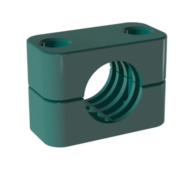

Profiled Design
Profiled Inside Surface with Tension Clearance
-
The Standard, Heavy, Twin, and Heavy Twin Series are all available.
-
Recommended for the safe installation of rigid pipes or tubes.
-
Outside diameters and nominal sizes in all popular sizes are available.
-
The grooves on the internal of the clamp bodies give a vibration/noise reduction and impact absorbing effect in the direction of the line.
-
The tube or pipe is held taut by the clearance S between the clamp halves.
-
To prevent the line from sliding, it should be utilized as a fixed point clamp.

Type H (Smooth)
Smooth Inside Surface without Tension Clearance
-
The Standard, Heavy, Twin, and Heavy Twin Series are all available.
-
Recommended for the safe installation of hoses or cables.
-
Outside diameters and nominal sizes in all popular sizes are available.
-
The hose or cable will not be damaged because to the smooth inside surface and chamfered edges.

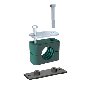
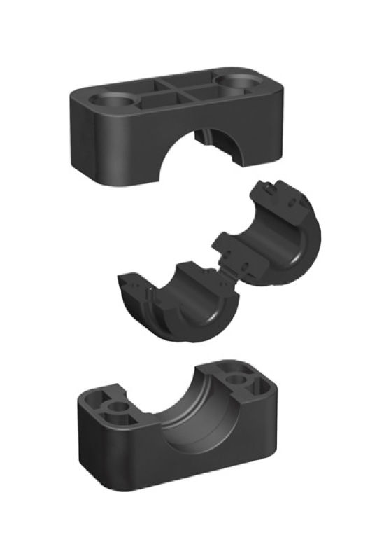
Type RI (with Elastomer Insert)
-
The Standard, Heavy, Twin, and Heavy Twin Series are all available.
-
Recommended for the extra-cautious installation of pipes, tubes, hoses or cables.
-
Outside diameters and nominal sizes in all popular sizes are available.
-
Thermoplastic Elastomer insert with a Shore-A hardness of 73 provides the most effective reduction of vibration and noise generated by vibration.
STANDARD CLAMP BODY MATERIALS
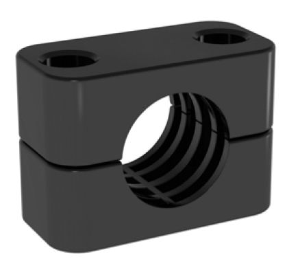
THERMOPLASTIC ELASTOMER BLACK

ALUMINIUM NATURAL
POLYAMIDE BLACK
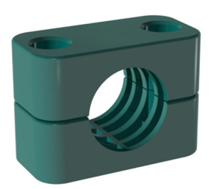
POLYPROPYLENE GREEN
METAL PARTS MATERIALS AND SURFACE FINISHINGS

MATERIALS
SURFACE FINISHINGS
After 1200 hours in the salt spray chamber, the original STAUFF Cover Plate with Zinc/Nickel-Coating has shown no symptoms of corrosion!
All metal parts (e.g. weld plates, cover plates, bolts, rail nuts, etc.) are made of Carbon Steel unless otherwise noted (surface finishing according to material code).
Apart from that, all metal parts are supplied ex-stock in stainless steel grades:
Stainless Steel V4A
-
1.4401 / 1.4571 (AISI 316 / 316 Ti)
-
Material code: W5
Unless otherwise specified, all carbon steel metal parts come with the following standard surface finishings:
Carbon Steel, zinc/nickel-plated
-
In the salt spray test to DIN EN ISO 9227, more than 1200 hours of resistance to red rust / base metal corrosion were achieved.
-
Hexavalent chromium Cr-free (VI)
-
RoHS compliant in accordance with 2002/95/EC (Restrictions of the Use of Hazardous Substances)
-
ELV compatible in accordance with 2000/53/EC (End of Life Vehicles Directive)
-
Material code: W3
BASIC INSTALLATION INSTRUCTIONS
Installation on Weld Plate
For all STAUFF Clamps that comply with DIN 3015, as well as most other series and many custom-designed special clamps, many types of weld plates are available.
-
Place the weld plates in their proper locations. Please double-check that these positions are appropriate for the anticipated loads.
-
To guarantee the best alignment, mark the positions of the weld plates.
-
Place the weld plates in place and weld them in place. Screws or bolts can also be used to secure elongated weld plates in place.
-
Half of the bottom clamp should be pressed against the weld plate.
-
Insert any sort of line, including pipe, tube, hose, cable, and so on.
-
Place the second clamp part on top, along with the cover plate (optional), and secure the clamp assembly with screws or bolts.

The bolt lengths for clamps according to DIN 3015 pertain to installation on weld plages and mouting rails, as well as multi-level (stacking) installation, unless otherwise stated. Different lengths may be necessary for direct installation.
Installation on Mounting Rail
STAUFF Mounting Rails come in a variety of heights. STAUFF Rail Nuts are available for all DIN 3015 STAUFF Clamps (Heavy Series up to STAUFF Group 6S only), as well as several custom-designed customized clamps.
-
Place the mounting rails in their proper locations. Please double-check that these foundations are adequate for the anticipated loads.
-
To achieve the optimal alignment, mark the positions of the mounting rails.
-
Place the mounting rails in place and weld them in place. Side-mounting brackets with screws or bolts can also be used to secure mounting rails in place.
-
Insert rail nuts into mounting rails and tighten (Standard and Twin Series) or slide in rail nuts (Heavy Series).
-
Half of the bottom clamp should be pushed onto the rail nuts.
-
Insert any sort of line, including pipe, tube, hose, cable, and so on.
-
Place the second clamp part on top, along with the cover plate (optional), and secure the clamp assembly with screws or bolts.

Before the clamp components are firmly fastened together, the exact placements of the clamp assemblies can be changed.
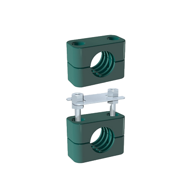
Multi-Level (Stacking) Installation
Stacking bolts allow clamps of identical group sizes to be assembled on many levels. The stacking bolts are prevented from twisting by safety locking plates inserted between the layers. Different group sizes (STAUFF Groups 2D to 5D) can be stacked in the Twin Series.
-
Half of the bottom clamp should be pressed against the weld plate or rail nuts.
-
Insert any sort of line, including pipe, tube, hose, cable, and so on.
-
Place the second clamp half in place.
-
Tighten the clamp halves in contact with the line over the full internal contact surface by inserting stacking bolts into the clamp assembly and tightening to the following torques:
-
Standard Series : 1 ... 2 N·m / .75 ... 1.5 ft·lb (hand-tightened)
-
Heavy Series : 5 N·m / 3.75 ft·lb
-
Twin Series : 1 ... 2 N·m / .75 ... 1.5 ft·lb (hand-tightened)
-
-
On top of the clamp assembly, place the safety locking plate.
-
Continue to the next level. Cover plate and hexagon head bolts will be used to assemble the top level.
Both weld plates and mounting rails can be used to mount STAUFF multi-level clamp systems (with rail nuts).
INSTALLATION NEXT TO PIPE BENDS, CONNECTORS / COUPLINGS & VALVES
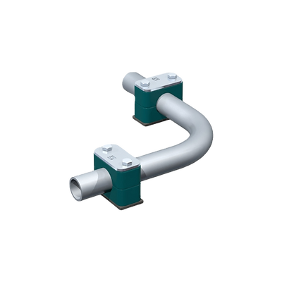
Please take note of the following details while installing STAUFF Clamps near pipe bends, connectors / couplings, and valves:
Pipe Bends
Connections / Couplings
STAUFF Clamps should be used to support pipe bends as close to the bends as possible. Furthermore, these clamps should be designed as fixed point clamps.
The first clamp should go right adjacent to the connector or coupling. The connector / coupler is therefore protected from vibrations.
Valves
If pipelines have valves, it is advised that support be provided in front of and behind the valves.